|
Learning about how to design |
● Learn more component issues
In our experience making plastic parts, there are common defects that appear from time to time. These defects can be caused by a range of factors including the type of plastic being molded, the design of the tool, and the control of process parameters during the molding cycle. For product designers, it’s important to be familiar with these common defects so that your design is optimized to prevent them when possible or to make tolerable allowances for them on the finished product.
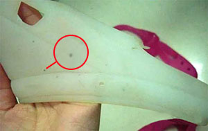
● Black Spots
When injecting light-colored plastic resins, there may be noticeable spots or flecks of darker-colored material embedded in the compound. These are caused by contamination of the plastic material, within the plastic injection molding machine, or the general environment at the time of processing. Practically speaking these may not be avoidable in all circumstances. |
 |
● Color Matching
Injection-molding colored plastics that are intended as a match for a customer-supplied sample, Pantone® or RAL color value may require mixing of pigments to achieve a near match for the sample. An exact match may not be possible due to a number of variables including plastic type, color, quantity, visual inspection conditions and environmental factors.
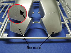
● Distortion
Part features such as wall thicknesses will cool at different rates depending on the thermal mass of the features. Areas of different thicknesses close to one another may produce surface undulations, waviness or other cosmetic variations.
● Draft Angle
This is a relief angle between the face of a part feature and the corresponding wall of the core/cavity, usually in parallel to the direction of the mold opening. We may recommend different angles dependent on the part’s geometry. A draft angle is needed to ensure that these features don’t scrape or seize against the tool wall as it is opened.
|
 |
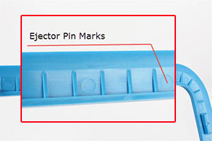
● Ejector Pin Position
Ejector pins are simply metal rods placed at strategic locations inside a mold tool. When an injection cycle is done and the tool opens, the pins protrude from the mold cavity and help to push the now completed part free.They are a necessary part of many mold tool designs but they will leave a corresponding shallow, circular mark on the part. Therefore, the pin location must be carefully chosen to avoid adversely affecting the fit and finish of the part.
|
 |
● Flash
Molten plastic can sometimes leak out of the mold, at the seam where the two halves meet. After cooling, this material will leave behind a paper-thin film clinging to the edge of a part. This excess plastic is easily removed and rarely leaves any blemish on the part, but it does require extra work and may slow down production while increasing processing costs.
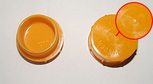
● Gate Marks
The gate is the nozzle from which liquid plastic is injected into a mold tool cavity. This area will leave a corresponding mark upon the finished part. It’s always best practice to therefore locate this mark in a place where it won’t affect the fit and finish, but this must be agreed upon before designing the mold tool.
|
 |
● Mismatch
Some plastic injected parts are formed by two mating halves that join at a parting line. If these corresponding sections are not in perfect alignment, the resulting part will have a slight mismatch. If a perfect match is not possible, this area can later be reworked via sanding and polishing, or the mismatch can be hidden with painting or surface texturing such as sandblasting.
|
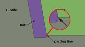 |
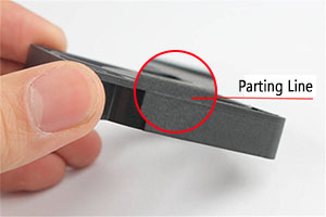
● Parting Lines
This is the line where the two halves of a mold tool separate to release the part from a single large cavity. A mark will be left behind on the part which may be unavoidable. Care should be taken to hide this line if possible or work it into the overall part geometry or final design. This line can also be hidden via post-processing, such as with painting, sanding or bead blasting. Rough surface textures will tend to hide parting lines more than glossy ones.
|
 |
●Texture
Heavily textured or coarse surfaces on the interior walls of mold cavities may cause them to grip the surface of the plastic part firmly after it cools. This can cause scratching or binding when the part is ejected. The best way to avoid this problem is by designing in a larger than normal relief angle, dependent on the degree of texturing.
●Tolerance And Shrinkage
All plastic resins will have differing amounts of shrinkage which must be accounted for in the design of the part and the mold tool. This deviation away from the nominal will have differing results in different areas, for example on threads, in holes, flat planes, etc.
|
 |
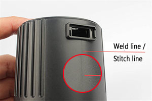
● Weld Lines
A weld line is an area where two separate channels of flowing liquid plastic meet and solidify within a mold cavity. The opposing fronts will partially cool as they meet and they may trap gas, creating a characteristic mark on the finished part surface.Weld lines may be unavoidable in many cases. They can be minimized to an acceptable degree by using conformal cooling channels where possible, by improving venting at the point of contact, or adjusting melt temperatures. Rough surface textures and/or painting will help to disguise weld lines.
|
 |
Plastic injection molding is still the fastest and most economical way to make thousands or even millions of plastic parts for every conceivable application. To get the best results requires thoughtful application of sound design principles early in the product development stage.
Learning about how to design for manufacturing is an important step in the journey of product development. Addressing issues before you start making the product will help you save time and money. Once you’re happy with your product design, send us your 3D file .
|
LOOK FORWARD TO YOUR SINCERE COOPERATION |
